Power Battery Solutions
  • Scopes
    • High performance E-racing
    • Retrofit
    • Zwaar materieel
    • Industrie
    • Maritiem
    • Specials & Kennis
  • Oplossingen
    • Luchtgekoeld elektrisch
    • Hybride elektrisch
    • Vloeistofgekoeld elektrisch
  • Hoe we werken
  • Technologie
    • Batterijtypes & celchemieën
    • Batterijmodules
    • Koeltechnologie
    • Batterijpakketten
    • Datasheets
    • Power Battery calculator
    • 3D-Modellen
  • Over ons
  • E-INSIGHTS
Contact
  • 9 safety standards for air-cooled battery systems

    When you’re pushing the limits on the track, every component of your racing machine needs to perform flawlessly under extreme conditions. This is especially true for air-cooled battery systems in high-performance applications, where temperatures soar and vibrations are relentless. Whether you’re retrofitting a sports car or building a Formula racing powerhouse, understanding the critical safety standards for these energy storage systems isn’t just about compliance—it’s about protecting your investment and ensuring peak performance when it matters most.

    The unique demands of racing environments make battery safety standards absolutely essential. Unlike standard automotive applications, racing scenarios subject battery packs to extreme G-forces, rapid temperature fluctuations, and intense electrical loads that can quickly overwhelm inadequately designed systems.

    1: Understanding air-cooled battery safety fundamentals

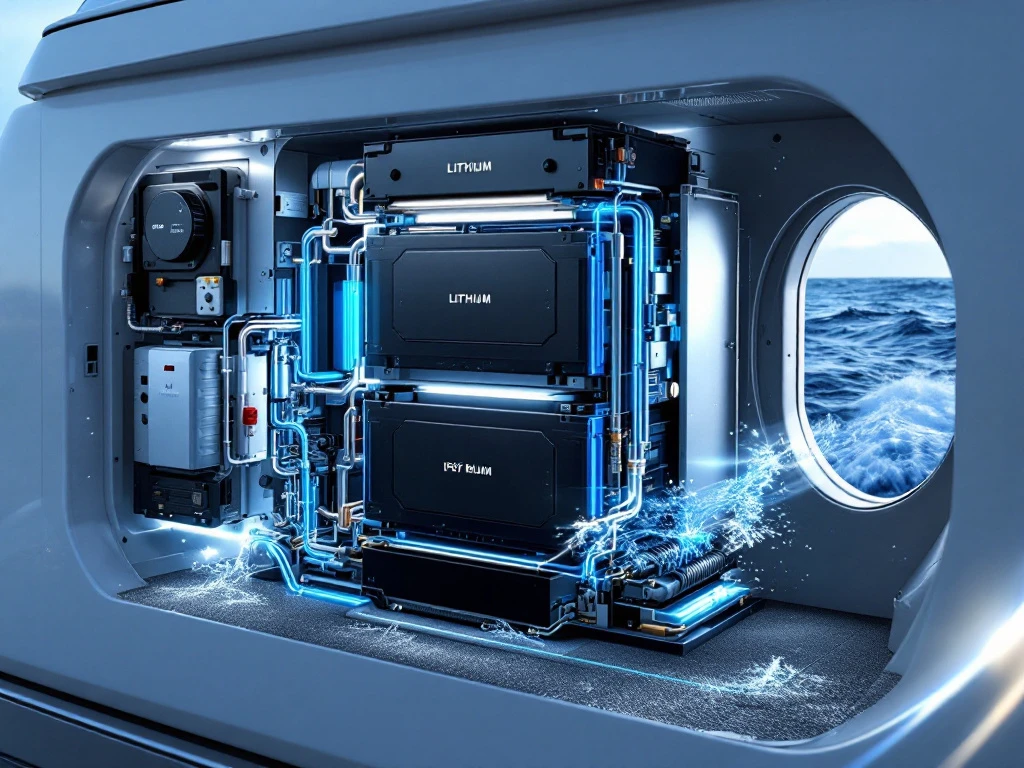
    Air-cooled battery systems rely on ambient air circulation to manage thermal conditions, making them particularly suitable for racing applications where weight reduction is paramount. These systems eliminate the complexity and weight penalties associated with liquid cooling whilst providing adequate thermal management for high-performance scenarios.

    The fundamental safety approach centres on preventing thermal runaway events, maintaining electrical integrity, and ensuring mechanical robustness under racing conditions. Unlike consumer applications, racing environments demand systems that can handle rapid acceleration, deceleration, and cornering forces that would challenge conventional designs.

    Safety standards for air-cooled systems must account for the unique heat dissipation characteristics and potential failure modes specific to air-based cooling. This includes managing hot spots, ensuring adequate airflow distribution, and maintaining safe operating temperatures even during extended high-load periods typical in racing scenarios.

    2: Thermal runaway prevention protocols

    Preventing thermal runaway in air-cooled systems requires sophisticated temperature monitoring and rapid response mechanisms. Battery pack safety depends on multi-layered thermal protection that can detect temperature anomalies before they cascade into dangerous situations.

    Temperature sensors must be strategically positioned throughout the battery pack, with particular attention to areas prone to heat accumulation. These sensors should trigger progressive responses: initial warnings, load reduction, and ultimately complete system shutdown if temperatures approach critical thresholds.

    Thermal barriers between cell groups help contain potential thermal events whilst allowing normal airflow for cooling. These barriers must withstand the mechanical stresses of racing whilst maintaining their protective properties over extended periods of vibration and temperature cycling.

    3: Airflow design and ventilation requirements

    Effective airflow design is the cornerstone of successful air-cooled battery systems in racing applications. The ventilation system must provide consistent cooling even when the vehicle is stationary or moving at low speeds, conditions that can challenge natural airflow patterns.

    Intake and exhaust positioning requires careful consideration of the vehicle’s aerodynamics and the racing environment. Battery cooling systems must account for potential blockages from debris, varying ambient temperatures, and the need to prevent moisture ingress whilst maintaining adequate ventilation.

    Fan systems, when required, should include redundancy and fail-safe mechanisms to ensure continued operation even if primary cooling fans malfunction. The electrical load of these systems must be factored into the overall energy management strategy to avoid compromising performance.

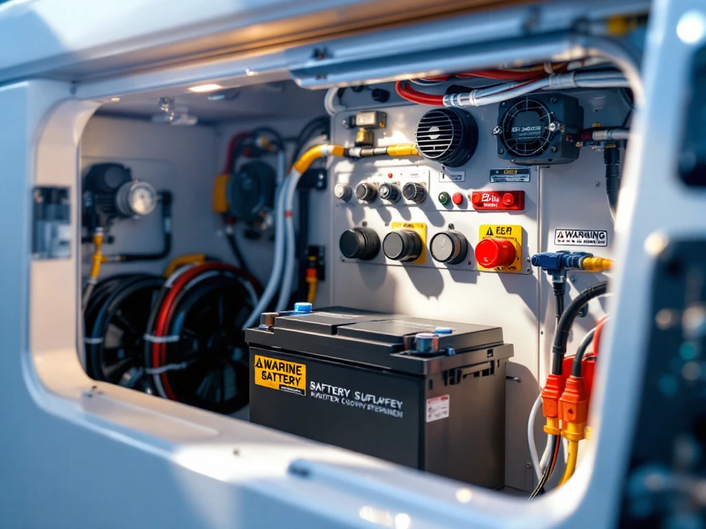
    4: Electrical isolation and insulation standards

    Racing environments subject electrical systems to extreme conditions that demand robust isolation and insulation protocols. High-voltage systems require multiple layers of protection to prevent dangerous electrical faults that could endanger drivers and support personnel.

    Insulation materials must maintain their properties across the wide temperature ranges encountered in racing, from cold morning practice sessions to the intense heat of competition. These materials must also resist degradation from vibration, chemical exposure, and the mechanical stresses of racing.

    Safety regulations typically mandate specific clearance distances and insulation resistance values that must be maintained throughout the system’s operational life. Regular testing protocols ensure these standards remain met despite the harsh operating environment.

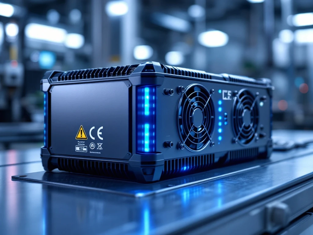
    5: Battery management system integration

    The Battery Management System (BMS) serves as the central nervous system for energy storage safety, monitoring every aspect of battery performance and health. In racing applications, the BMS must make split-second decisions whilst providing detailed telemetry for performance optimisation.

    Cell balancing becomes critical in high-performance applications where uneven loads can quickly lead to cell degradation or failure. The BMS must actively manage individual cell voltages whilst maintaining overall pack performance under rapidly changing load conditions.

    Emergency shutdown capabilities must be integrated with the vehicle’s safety systems, allowing for immediate disconnection in the event of an accident or system malfunction. These systems require fail-safe designs that function even when primary power or communication systems are compromised.

    6: Fire suppression measures for air-cooled systems

    Fire detection and suppression systems for air-cooled battery installations must account for the unique characteristics of battery fires and the racing environment. Traditional fire suppression methods may prove inadequate for lithium-ion battery fires, requiring specialised approaches.

    Detection systems must differentiate between normal operational heat and dangerous thermal events. Multi-sensor approaches using temperature, smoke, and gas detection provide comprehensive monitoring whilst minimising false alarms that could interrupt racing activities.

    Suppression systems should focus on cooling and containment rather than traditional fire suppression methods. Modular battery systems allow for isolation of affected sections whilst maintaining operation of unaffected areas, crucial for safely exiting the racing environment.

    7: Mechanical protection and housing standards

    Racing applications subject battery housings to extreme mechanical stresses that far exceed normal automotive requirements. Impact resistance must account for potential collisions, debris strikes, and the constant vibration of high-performance engines and road surfaces.

    Housing materials must balance protection with weight considerations, often requiring advanced composites or specialised alloys. The structural design must maintain integrity even after minor impacts whilst allowing for thermal expansion and contraction of internal components.

    Mounting systems require particular attention, as they must transfer the mechanical loads safely to the vehicle structure whilst allowing for controlled deformation in severe impact scenarios. This protects both the battery system and vehicle occupants.

    8: Environmental sealing and ingress protection

    Air-cooled systems face unique challenges in environmental sealing, as they must allow airflow whilst preventing ingress of moisture, dust, and debris. IP rating requirements must balance protection with cooling effectiveness.

    Sealing systems must maintain their integrity across the temperature ranges and mechanical stresses encountered in racing. This includes consideration of thermal cycling effects on seals and gaskets, which can lead to premature failure if not properly specified.

    Battery design standards typically require testing under conditions that simulate racing environments, including water spray, dust exposure, and pressure cycling that mimics the effects of high-speed operation.

    9: Emergency response and maintenance protocols

    Comprehensive emergency response procedures must be established for any racing team utilising air-cooled battery systems. These protocols should address various scenarios from minor system faults to major incidents requiring immediate evacuation.

    Maintenance procedures require specialised training and equipment to safely service high-voltage systems in racing environments. Personnel protection measures include appropriate personal protective equipment and isolation procedures that ensure safe working conditions.

    Regular inspection schedules must account for the accelerated wear patterns typical in racing applications. This includes monitoring of connections, insulation integrity, and cooling system effectiveness to prevent failures during critical racing periods. However, many teams struggle with implementation due to common performance misconceptions that can lead to inadequate safety measures.

    Building your safety-first racing advantage

    Implementing these nine safety standards transforms your air-cooled battery system from a potential liability into a competitive advantage. The integration of comprehensive safety measures not only protects your team and equipment but also ensures consistent performance when victory margins are measured in milliseconds.

    The investment in proper safety standards pays dividends through reduced downtime, improved reliability, and the confidence that comes from knowing your systems can handle whatever the track throws at them. As racing technology continues to evolve, these fundamental safety principles remain the foundation upon which successful high-performance battery systems are built.

    Ready to elevate your racing programme with properly engineered battery safety systems? We specialise in developing custom solutions that meet the unique demands of high-performance applications. Contact us to discuss how we can help you implement these critical safety standards in your next racing project.

  • 7 fire suppression methods for battery installations

    When you’re pushing the limits on the track, every component of your high-performance vehicle needs to be reliable and safe. This includes your custom battery systems, which can pose significant fire risks if not properly protected. Battery fires in racing applications aren’t just about equipment loss—they can endanger lives and end seasons before they’ve truly begun.

    Fire suppression in battery installations has become increasingly critical as energy storage systems grow more powerful and compact. Understanding your options for battery fire prevention can mean the difference between a minor incident and a catastrophic failure that puts your entire racing programme at risk.

    1: Water-based suppression systems for battery fires

    Water mist and fine water spray systems represent one of the most accessible fire suppression systems for battery installations. These systems work by rapidly cooling the battery cells and creating a barrier of steam that helps displace oxygen around the fire source. The key advantage lies in their ability to penetrate deep into battery compartments where traditional sprinkler systems might struggle.

    However, water-based systems require careful consideration in racing applications. The electrical safety implications mean you’ll need proper isolation protocols and waterproof enclosures for critical components. Modern water mist systems use significantly less water than traditional sprinklers, reducing the risk of electrical damage whilst maintaining effectiveness against lithium battery safety threats.

    For racing teams, the installation complexity and weight considerations make water-based systems more suitable for pit areas and charging stations rather than in-vehicle applications. The rapid cooling effect can help prevent thermal runaway from spreading between battery modules, making them particularly valuable for larger energy storage installations.

    2: Inert gas flooding systems

    Nitrogen, argon, and CO2 flooding systems work by reducing oxygen levels below the threshold needed for combustion. These systems are particularly effective in enclosed battery compartments where you can maintain the necessary gas concentration. The deployment mechanism typically involves rapid release through strategically placed nozzles that ensure even distribution throughout the protected space.

    Industrial battery safety applications often favour inert gas systems because they leave no residue and won’t damage sensitive electronic components. For racing applications, the weight and space requirements of gas storage cylinders need careful consideration, but the clean suppression method makes them ideal for protecting high-value custom battery systems.

    The effectiveness depends on achieving the right gas concentration quickly enough to suppress the fire before thermal runaway spreads. Modern systems include sophisticated monitoring to ensure proper deployment and can be integrated with automatic detection systems for rapid response.

    3: Aerosol-based fire suppression technology

    Condensed aerosol systems release microscopic particles that interfere with the chemical chain reaction of combustion. These systems are compact, lightweight, and don’t require extensive piping or storage tanks, making them particularly attractive for racing applications where every kilogram matters.

    The activation methods range from thermal triggers that respond to heat to electrical activation integrated with your vehicle’s safety systems. Unlike water or foam, aerosol suppression won’t cause additional damage to your battery installation or surrounding components, which is crucial when dealing with expensive racing electronics.

    For custom battery systems in racing applications, aerosol technology offers excellent coverage in confined spaces. The particles remain suspended for extended periods, providing ongoing suppression even if the initial fire source reignites. This extended protection is particularly valuable given the tendency of lithium batteries to experience multiple thermal events.

    4: Foam suppression systems for large installations

    Specialised foam agents designed for electrical fires create a blanket that both cools the battery cells and prevents oxygen from reaching the combustion zone. These systems are most effective in large-scale installations such as pit area charging stations or workshop environments where racing teams maintain their energy storage systems.

    The application techniques vary depending on the battery chemistry and installation layout. Modern foam systems can be tailored to specific lithium chemistries, with different agents optimised for different cell types. The foam selection criteria include factors such as electrical conductivity, environmental impact, and cleanup requirements.

    Fire protection methods using foam are particularly effective because they provide both immediate suppression and longer-term protection against reignition. For racing teams managing multiple vehicles and charging systems, foam suppression offers scalable protection that can cover large areas efficiently.

    5: Thermal barriers and passive fire protection

    Thermal barriers work by containing heat and preventing fire spread between battery modules. These passive systems include fire-resistant enclosures, specialised insulation materials, and compartmentalisation strategies that can buy crucial time for other suppression systems to activate.

    The effectiveness of thermal barriers lies in their ability to slow down battery thermal runaway propagation. By isolating individual battery modules or sections, you can prevent a single cell failure from cascading through your entire energy storage system. This compartmentalisation approach is particularly valuable in racing applications where battery packs are often custom-designed with unique layouts.

    Modern thermal barrier materials can withstand extreme temperatures whilst remaining lightweight enough for racing applications. The integration with active suppression systems creates multiple layers of protection, significantly improving overall energy storage safety in high-performance environments.

    6: Automatic detection and early warning systems

    Early detection systems form the foundation of effective fire suppression strategies. Smoke detection, thermal sensors, and gas detection systems can identify potential problems before they develop into full fires. For battery installations, specialised sensors can detect the off-gassing that often precedes thermal runaway events.

    Integrated monitoring solutions combine multiple detection methods with automated response capabilities. These systems can simultaneously shut down charging, activate suppression systems, and alert team members to potential dangers. The rapid response capability is crucial in racing environments where seconds can make the difference between a contained incident and a major fire.

    Modern detection systems can differentiate between normal operational heating and dangerous thermal events, reducing false alarms whilst maintaining sensitivity to genuine threats. This precision is essential in racing applications where unnecessary shutdowns can impact performance and race preparation schedules. Additionally, implementing critical ventilation requirements works alongside detection systems to prevent dangerous gas accumulation and maintain safe operating conditions.

    7: Manual suppression tools and emergency procedures

    Portable fire extinguishers specifically rated for electrical fires remain an essential component of any comprehensive fire safety strategy. Class C extinguishers using CO2 or dry chemical agents are suitable for battery fires, though specialised lithium battery extinguishers offer improved effectiveness for modern energy storage systems.

    Emergency shutdown procedures should be clearly defined and regularly practised by all team members. These procedures include methods for safely disconnecting power, activating manual suppression systems, and coordinating with emergency services. The manual intervention techniques need to account for the unique hazards of battery fires, including toxic gas emissions and reignition potential.

    Training programmes should cover the proper use of manual suppression tools and the recognition of situations where evacuation is the safest option. For racing teams, these procedures need to be adapted for both workshop and trackside environments, with different protocols for different scenarios.

    Building your comprehensive fire safety strategy

    Creating an effective fire safety strategy for your racing operation requires careful consideration of all these suppression methods and how they work together. The most robust approach typically combines multiple systems—perhaps thermal barriers for passive protection, automatic detection for early warning, and aerosol or gas suppression for active fire fighting.

    The integration with your existing safety systems should be seamless, with clear protocols for different scenarios and regular testing to ensure everything works when needed. Your fire safety strategy should evolve with your battery technology and racing requirements, with regular reviews to incorporate new suppression technologies and lessons learned from the field.

    Remember that the best fire suppression system is one that never needs to be used. Proper battery management, regular maintenance, and adherence to safety protocols remain your first line of defence. When you’re ready to develop a comprehensive fire safety strategy tailored to your specific racing applications and custom energy storage requirements, don’t hesitate to contact us for expert guidance on protecting your investment and your team.

  • What are battery safety standards for marine applications?

    Battery safety standards for marine applications encompass specialised regulations and protocols designed to protect watercraft electrical systems from the unique challenges of maritime environments. These standards include international certifications like IEC 62619, UL 1973, and DNV GL regulations, which address saltwater corrosion, humidity exposure, vibration resistance, and thermal management requirements specific to marine energy storage systems.

    Understanding marine battery safety requirements

    Marine battery safety requirements represent a critical foundation for any watercraft electrical system, addressing the unique hazards present in maritime environments. Unlike terrestrial applications, boat battery safety must account for constant moisture exposure, saltwater corrosion, and the dynamic forces experienced at sea.

    Watercraft batteries face challenges that simply don’t exist in land-based applications. The combination of saltwater spray, humidity levels often exceeding 90%, and continuous vibration creates an environment where standard battery systems would quickly fail or pose serious safety risks.

    Maritime battery systems require specialised safety protocols because failure at sea can have catastrophic consequences. When you’re miles from shore, a battery fire or electrical failure isn’t just an inconvenience, it’s a life-threatening emergency. This reality drives the development of stringent marine battery regulations that prioritise both performance and safety.

    What are the main safety standards for marine batteries?

    The primary safety standards for maritime battery systems include IEC 62619 for lithium-ion batteries, UL 1973 for stationary energy storage, and DNV GL maritime regulations, each addressing specific aspects of marine energy storage safety and performance requirements.

    IEC 62619 establishes safety requirements for lithium-ion batteries used in industrial applications, including marine environments. This standard covers thermal stability, electrical safety, and mechanical integrity under various stress conditions typical of maritime use.

    UL 1973 focuses on stationary energy storage systems but applies to marine installations where batteries remain fixed within the vessel. This certification addresses fire safety, electrical protection, and environmental resistance requirements.

    StandardFocus AreaKey Requirements
    IEC 62619Lithium-ion safetyThermal stability, electrical protection
    UL 1973Energy storage systemsFire safety, environmental resistance
    DNV GLMaritime applicationsMarine-specific hazards, certification
    IMO GuidelinesInternational shippingTransport safety, handling procedures

    DNV GL provides maritime-specific certifications that address the unique challenges of marine environments, including enhanced vibration resistance and saltwater exposure protection. These regulations work alongside international maritime standards that establish comprehensive requirements for global shipping operations and cross-border compliance.

    How do marine environments affect battery safety requirements?

    Marine environments significantly elevate battery safety requirements due to saltwater corrosion, extreme humidity, temperature fluctuations, and constant vibration, necessitating enhanced protection systems and specialised materials not required in terrestrial applications.

    Saltwater exposure creates corrosive conditions that can rapidly degrade battery components and electrical connections. This corrosion risk requires marine battery systems to incorporate corrosion-resistant materials and protective coatings throughout their construction.

    Temperature fluctuations in marine environments can be extreme, with batteries potentially experiencing freezing conditions at night and high temperatures during sunny days. These thermal cycles stress battery chemistry and require robust thermal management systems.

    Humidity levels at sea regularly exceed those found on land, creating condensation risks that can lead to electrical shorts or component degradation. Marine battery regulations therefore mandate superior moisture protection and ventilation systems.

    Constant vibration from wave action and engine operation subjects batteries to mechanical stresses that can loosen connections, damage internal components, or cause structural failures. This reality drives requirements for enhanced mounting systems and vibration-resistant designs.

    What safety features must marine batteries include?

    Marine batteries must incorporate battery management systems, thermal protection, waterproof enclosures, emergency shutdown mechanisms, and specialised ventilation systems to meet maritime safety standards and protect against the unique hazards of marine environments.

    Battery management systems serve as the brain of marine energy storage, continuously monitoring cell voltages, temperatures, and current flows. These systems automatically disconnect power if dangerous conditions develop, preventing thermal runaway or electrical fires.

    Thermal protection includes both passive and active cooling systems designed to maintain safe operating temperatures even under extreme marine conditions. This protection often involves liquid cooling systems that can handle the demanding thermal cycles experienced at sea.

    Waterproof enclosures with appropriate IP ratings protect internal components from saltwater intrusion whilst allowing necessary ventilation. These enclosures must balance protection with the need for heat dissipation and gas venting.

    Emergency shutdown mechanisms provide manual and automatic methods to disconnect battery power in emergency situations. These systems must remain accessible and functional even when other electrical systems fail.

    How are marine battery systems tested for safety compliance?

    Marine battery systems undergo rigorous testing including vibration testing, salt spray resistance evaluation, thermal cycling, electrical safety verification, and environmental stress testing to ensure compliance with maritime safety standards before certification approval.

    Vibration testing simulates the constant motion experienced at sea, subjecting batteries to various frequencies and amplitudes that replicate real-world marine conditions. This testing ensures connections remain secure and internal components don’t shift or fail.

    Salt spray resistance testing exposes battery systems to accelerated corrosion conditions, verifying that protective coatings and seals maintain their integrity over extended periods of saltwater exposure.

    Thermal cycling tests subject batteries to repeated temperature changes, ensuring the system can handle the expansion and contraction cycles common in marine environments without compromising safety or performance.

    Electrical safety verification includes insulation resistance testing, ground fault protection verification, and arc fault detection system validation to ensure the battery system won’t create electrical hazards aboard the vessel.

    What are the installation requirements for safe marine battery systems?

    Safe marine battery installation requires proper compartment ventilation, secure mounting systems, marine-grade electrical connections, accessible maintenance points, and integration with vessel safety systems to ensure compliance with maritime regulations and operational safety.

    Compartment ventilation must provide adequate airflow to remove any gases generated during battery operation whilst preventing the ingress of saltwater or excessive moisture. This ventilation system often includes both passive and active components.

    Mounting systems must secure batteries against the dynamic forces experienced at sea, including sudden impacts from large waves or emergency manoeuvres. These systems typically involve multiple mounting points and shock-absorbing materials.

    Electrical connections require marine-grade components rated for the harsh maritime environment, including corrosion-resistant terminals, waterproof junction boxes, and properly sized conductors that can handle both normal operations and fault conditions.

    Integration with vessel safety systems ensures the battery system communicates with fire suppression systems, emergency power management, and navigation equipment to maintain vessel safety under all conditions.

    Key takeaways for marine battery safety compliance

    Marine battery safety compliance centres on understanding that maritime environments demand significantly higher safety standards than terrestrial applications, requiring specialised certifications, enhanced protection systems, and rigorous testing protocols to ensure safe operation at sea.

    The most critical compliance factors include obtaining appropriate certifications such as IEC 62619 and DNV GL approval, implementing comprehensive battery management systems, and ensuring proper installation with adequate ventilation and secure mounting.

    Best practices for maintaining compliance involve regular inspection of protective systems, verification of ventilation effectiveness, and ongoing monitoring of battery performance parameters to identify potential issues before they become safety hazards.

    Successful marine battery implementation requires collaboration between battery manufacturers, vessel designers, and certification bodies to ensure all safety requirements are met whilst achieving the performance demands of maritime applications.

    For racing applications and high-performance marine systems, these safety standards become even more critical due to the extreme operating conditions and performance demands. If you’re developing a marine battery system that requires custom engineering solutions to meet these stringent safety requirements, we encourage you to contact our team to discuss your specific application needs and compliance requirements.

  • What are the most common battery system failure modes?

    Battery system failure modes encompass several critical issues that can compromise energy storage performance and safety. The most common failures include thermal runaway, cell balancing problems, battery management system malfunctions, electrolyte degradation, mechanical stress damage, and natural aging processes. Understanding these failure modes is essential for designing reliable custom battery solutions that maintain optimal performance in demanding applications.

    Understanding battery system failure modes in energy storage applications

    Battery system failure modes represent critical vulnerabilities that can lead to performance degradation, safety hazards, and complete system shutdown in energy storage applications. These failures become particularly concerning in high-performance environments where reliability is paramount.

    Custom modular energy storage systems face unique challenges due to their specialised applications. Racing applications demand extreme power delivery under harsh conditions, whilst industrial equipment requires consistent performance over extended periods. Each environment presents distinct stress factors that can trigger different battery pack failures.

    Identifying potential failure modes early allows engineers to implement preventive measures during the design phase. This proactive approach significantly reduces the risk of catastrophic failures and extends system lifespan, making it essential for applications where downtime is not acceptable.

    What causes thermal runaway in battery systems?

    Thermal runaway occurs when a battery cell generates heat faster than it can dissipate it, creating a self-accelerating cycle that can lead to fire, explosion, or toxic gas release. This represents one of the most dangerous battery system failure modes.

    Overcharging stands as the primary trigger for thermal runaway events. When cells receive excessive voltage or current, they generate excess heat whilst breaking down internal components. Manufacturing defects, such as contaminated separators or improper cell assembly, can create internal short circuits that initiate thermal events.

    Physical damage from impacts, crushing, or penetration can compromise cell integrity and trigger immediate thermal reactions. Extreme temperature conditions, particularly sustained exposure to high ambient temperatures, can push cells beyond their thermal limits and initiate runaway conditions.

    Prevention requires robust thermal management systems, proper charging protocols, and comprehensive monitoring. Quality control during manufacturing and careful handling during installation further reduce thermal runaway risks in energy storage system problems.

    How do cell balancing issues affect battery pack performance?

    Cell balancing issues occur when individual cells within a battery pack operate at different voltage or capacity levels, leading to reduced performance, shortened lifespan, and potential safety concerns.

    Voltage disparities between cells force the battery management system to limit charging and discharging to protect the weakest cell. This restriction prevents the pack from utilising its full capacity and power potential, significantly impacting overall performance in demanding applications.

    Capacity mismatches develop when cells age at different rates or have varying manufacturing tolerances. Stronger cells must compensate for weaker ones, leading to accelerated degradation of the entire pack. This imbalance becomes more pronounced over time, creating a cascading effect that reduces system reliability.

    Temperature variations across the pack can exacerbate balancing problems. Cells operating at different temperatures exhibit different electrical characteristics, making it challenging to maintain uniform performance across all cells in modular energy storage systems.

    Why do battery management systems fail and how can you prevent it?

    Battery management system failures typically result from sensor malfunctions, communication errors, software bugs, or hardware degradation that compromise the system’s ability to monitor and control battery operations safely.

    Sensor malfunctions represent a common failure mode where temperature, voltage, or current sensors provide inaccurate readings. These false readings can lead to inappropriate charging decisions, inadequate thermal management, or failure to detect dangerous conditions before they escalate.

    Communication errors between the battery management system and external devices can prevent proper coordination of charging, discharging, and safety functions. Software bugs may cause unexpected behaviour, whilst hardware degradation over time can compromise system reliability.

    Prevention strategies include redundant sensor systems, regular software updates, comprehensive testing protocols, and robust hardware design. Implementing fail-safe mechanisms ensures the system defaults to safe operating modes when anomalies are detected, protecting both the battery and connected equipment.

    What are the signs of electrolyte degradation in battery cells?

    Electrolyte degradation manifests through capacity loss, increased internal resistance, gas generation, and reduced voltage stability, indicating chemical breakdown within battery cells that compromises performance and safety.

    Capacity loss represents the most noticeable symptom, where cells can no longer store or deliver their rated energy. This degradation occurs gradually as electrolyte components break down, reducing the cell’s ability to facilitate ion movement between electrodes.

    Increased internal resistance causes cells to generate more heat during operation and reduces their ability to deliver high currents. This symptom often accompanies voltage instability, where cells struggle to maintain consistent voltage levels under load.

    Gas generation from electrolyte breakdown can cause cell swelling, increased pressure, and potential safety hazards. Advanced battery degradation monitoring systems can detect these early warning signs through impedance measurements and thermal analysis, allowing for proactive maintenance.

    How does mechanical stress cause battery system failures?

    Mechanical stress failures result from vibration damage, thermal expansion issues, connection failures, and structural integrity problems that physically compromise battery components and electrical connections.

    Vibration damage occurs particularly in mobile applications where constant movement can loosen connections, crack cell housings, or damage internal components. Racing applications and construction equipment face especially severe vibration challenges that require robust mechanical design.

    Thermal expansion creates stress as components expand and contract with temperature changes. Different materials expand at different rates, potentially causing mechanical failures at connection points or within cell structures over repeated thermal cycles.

    Connection failures represent a critical vulnerability where electrical connections deteriorate due to corrosion, loosening, or mechanical fatigue. These failures can create high-resistance connections that generate heat and potentially trigger more serious problems.

    Proper mechanical design includes vibration dampening, flexible connections, appropriate material selection, and regular inspection protocols to identify potential issues before they cause system failures.

    What role does aging play in battery system deterioration?

    Aging encompasses both calendar aging (time-based degradation) and cycle aging (use-based degradation) that naturally reduce battery capacity, power capability, and overall performance over the system’s operational life.

    Calendar aging occurs regardless of usage patterns, driven by chemical reactions within cells that gradually break down active materials and electrolyte components. This process accelerates at higher temperatures and can significantly impact batteries in storage or low-use applications.

    Cycle aging results from repeated charging and discharging operations that stress cell components. Each cycle causes microscopic changes to electrode materials and electrolyte composition, gradually reducing the cell’s ability to store and deliver energy.

    Power fade and impedance growth accompany capacity reduction, limiting the battery’s ability to deliver high currents or respond quickly to load changes. These aging effects become particularly problematic in high-performance applications where consistent power delivery is critical.

    Understanding aging patterns allows for better system design, appropriate sizing, and realistic performance expectations throughout the battery’s operational life.

    Key strategies for preventing battery system failures in custom applications

    Effective failure prevention requires comprehensive design considerations, continuous monitoring techniques, proactive maintenance protocols, and robust safety measures tailored to specific application requirements.

    Proper thermal management stands as the foundation of battery safety, incorporating adequate cooling systems, temperature monitoring, and thermal barriers to prevent dangerous temperature excursions. Custom battery solutions must account for the specific thermal challenges of their intended applications.

    Advanced monitoring systems provide early warning of potential problems through continuous measurement of key parameters including voltage, current, temperature, and impedance. These systems enable predictive maintenance and prevent minor issues from escalating into major failures.

    Regular maintenance protocols include connection inspections, performance testing, and systematic replacement of aging components. Documentation of maintenance activities helps identify patterns and optimise future designs.

    Quality control during manufacturing and installation ensures systems meet specification requirements and reduces the likelihood of early failures. Proper training for personnel handling battery systems further minimises risks associated with improper operation or maintenance.

    To systematically address these potential failures, conducting a comprehensive hazard analysis provides a structured approach to identifying and mitigating risks before they impact system performance. Understanding these failure modes and implementing appropriate prevention strategies is crucial for developing reliable energy storage solutions. If you’re developing a custom battery system for high-performance applications and need expert guidance on failure prevention strategies, please contact our engineering team to discuss your specific requirements.

  • What additional safety measures are needed for boat batteries?

    Boat batteries require specialised safety measures beyond standard automotive applications due to the harsh marine environment. Essential additional safety measures include proper ventilation systems to prevent gas accumulation, waterproof enclosures with appropriate IP ratings, corrosion-resistant terminals and connections, secure mounting systems to handle marine vibrations, and comprehensive monitoring equipment including battery management systems and disconnect switches for emergency situations.

    Understanding boat battery safety fundamentals

    Marine environments present unique challenges that make boat battery safety fundamentally different from land-based applications. The combination of saltwater exposure, constant moisture, vibration from wave action, and confined spaces creates a perfect storm of conditions that can compromise battery performance and safety.

    Saltwater corrosion poses the most significant threat to marine battery systems. Unlike freshwater, saltwater conducts electricity and accelerates corrosion of metal components at an alarming rate. This creates potential failure points in terminals, connections, and housing materials that could lead to dangerous situations.

    The confined nature of boat battery compartments compounds these challenges. Poor ventilation can lead to dangerous gas accumulation, whilst limited access makes regular maintenance more difficult. Temperature fluctuations from engine heat and ambient conditions further stress battery components, requiring robust thermal management solutions.

    What makes boat battery safety different from automotive applications?

    Marine battery environments face significantly harsher conditions than automotive applications, requiring specialised safety protocols. Whilst car batteries deal with relatively stable conditions under the bonnet, boat batteries must withstand constant moisture, salt spray, and dramatic temperature variations.

    Humidity levels in marine environments consistently exceed 80%, compared to typical automotive environments that rarely sustain such moisture levels. This persistent dampness accelerates corrosion and can cause electrical faults that would never occur in automotive applications.

    Regulatory requirements also differ substantially between marine and automotive sectors. Marine electrical systems must comply with specific watercraft safety standards that address fire prevention, electrical isolation, and emergency disconnect procedures. These regulations recognise the unique risks of being stranded at sea with electrical failures.

    Vibration patterns in marine applications are also more complex than automotive environments. Boats experience multi-directional forces from waves, creating stress patterns that can loosen connections and damage battery internals over time.

    How should boat batteries be properly ventilated and positioned?

    Proper battery ventilation in boats requires dedicated airflow systems that prevent hydrogen gas accumulation whilst protecting against moisture ingress. Battery compartments must have both intake and exhaust ventilation, with air movement sufficient to dilute any gases produced during charging cycles.

    Positioning boat batteries requires careful consideration of weight distribution and accessibility. Batteries should be mounted as low as possible in the vessel to maintain stability, but never in bilge areas where they could be submerged. The ideal location provides easy access for maintenance whilst remaining protected from spray and flooding.

    Ventilation systems should include spark-proof fans when mechanical ventilation is necessary. Natural convection ventilation is preferred where possible, using strategically placed vents that allow air circulation without compromising waterproofing. Battery compartments must never share ventilation with engine spaces or living areas.

    Spacing considerations are crucial for both ventilation and safety. Batteries require adequate clearance around all sides for air circulation and thermal management. This spacing also provides access for maintenance and emergency disconnection procedures.

    What waterproofing and corrosion protection do marine batteries need?

    Marine battery protection requires comprehensive waterproofing measures starting with appropriate IP ratings for all electrical components. Battery enclosures should meet minimum IP65 standards, with IP67 preferred for areas exposed to spray or potential submersion.

    Terminal protection involves multiple layers of defence against corrosion. Marine-grade terminal protectors, dielectric grease, and corrosion inhibitors create barriers against salt and moisture. All connections must use tinned copper conductors and marine-grade terminals designed for saltwater environments.

    Cable sealing requires special attention at entry and exit points from battery compartments. Marine-grade cable glands and sealed pass-throughs prevent moisture ingress whilst maintaining flexibility for thermal expansion. Heat-shrink tubing with adhesive lining provides additional protection at connection points.

    Protection LevelIP RatingApplicationProtection Against
    BasicIP54Dry compartmentsDust and splashing
    StandardIP65Engine compartmentsJets of water
    EnhancedIP67Exposed areasTemporary submersion
    MaximumIP68Below waterlineContinuous submersion

    How do you safely install and maintain boat battery systems?

    Safe boat battery installation begins with proper mounting systems that secure batteries against marine motion whilst allowing for thermal expansion. Battery boxes must be constructed from non-conductive, corrosion-resistant materials with adequate drainage and ventilation provisions.

    Installation procedures require careful attention to electrical connections and routing. All wiring must be supported at regular intervals to prevent chafing and fatigue from vessel movement. Connections should be made with marine-grade terminals and protected with appropriate covers and sealants.

    Regular maintenance schedules for marine batteries are more intensive than automotive applications. Monthly visual inspections should check for corrosion, loose connections, and physical damage. Quarterly maintenance includes cleaning terminals, checking electrolyte levels where applicable, and testing charging system performance.

    Inspection protocols must include thermal imaging where possible to identify hot spots that indicate poor connections or failing components. Load testing should be performed annually to verify battery capacity and identify deteriorating cells before they cause system failures.

    What safety equipment and monitoring should accompany boat batteries?

    Marine electrical safety requires comprehensive monitoring and safety equipment beyond the battery system itself. Battery monitoring systems should track voltage, current, temperature, and state of charge to provide early warning of potential problems.

    Disconnect switches are mandatory safety equipment that must be easily accessible in emergency situations. These switches should be rated for the full system current and positioned where they can be operated quickly without exposing personnel to electrical hazards.

    Fire suppression considerations for battery compartments include both detection and suppression systems. Smoke detectors specifically designed for marine environments can provide early warning, whilst appropriate fire suppression agents must be selected based on battery chemistry and compartment ventilation.

    Alarm systems should integrate with vessel monitoring systems to alert crew to battery-related issues. These alarms must be audible over engine noise and weather conditions, with visual indicators visible from the helm position.

    Key takeaways for boat battery safety implementation

    Implementing comprehensive marine battery safety requires a systematic approach that addresses the unique challenges of the marine environment. Critical safety measures include robust waterproofing, proper ventilation, secure mounting, and comprehensive monitoring systems that work together to ensure reliable operation.

    Regulatory compliance varies by vessel type and operating area, but all marine battery installations should exceed minimum standards where practical. Regular maintenance and inspection schedules are essential for identifying potential problems before they become safety hazards.

    Best practices for maintaining safe marine battery systems emphasise prevention over reaction. Proper initial installation, quality components, and regular maintenance create reliable systems that perform safely throughout their service life.

    The investment in proper marine battery safety measures pays dividends in system reliability and crew safety. Whether you’re operating high-performance battery design applications or commercial vessels, implementing these safety measures ensures your electrical systems perform when you need them most. If you’re planning a marine battery installation or upgrade, we encourage you to contact our team for guidance on implementing these critical safety measures in your specific application.

  • What is battery system hazard analysis?

    Battery system hazard analysis is a systematic process that identifies, evaluates, and mitigates potential risks in energy storage systems. This comprehensive battery safety assessment examines thermal, electrical, mechanical, and chemical hazards to prevent failures and ensure safe operation. For custom modular systems, particularly in high-performance applications like racing, proper hazard analysis is essential for protecting both equipment and personnel whilst maintaining optimal performance standards.

    Understanding battery system hazard analysis fundamentals

    Battery system hazard analysis is a structured methodology for identifying and evaluating potential risks within energy storage systems. This process systematically examines every component, connection, and operational scenario to predict where failures might occur and what consequences could follow.

    The core purpose centres on proactive risk identification rather than reactive problem-solving. By analysing potential failure modes before they occur, engineers can design appropriate safeguards and mitigation strategies. This approach proves particularly vital for custom modular energy storage systems where standard safety protocols may not address unique design requirements.

    For industrial applications, hazard analysis encompasses multiple risk categories including thermal events, electrical faults, mechanical damage, and chemical exposure. Each category requires specific evaluation techniques and safety measures tailored to the application’s operational environment and performance demands.

    What are the main hazards in battery systems?

    Thermal runaway represents the most critical hazard in lithium battery systems, where overheating triggers a chain reaction leading to fire or explosion. This phenomenon can result from overcharging, physical damage, manufacturing defects, or exposure to extreme temperatures.

    Electrical faults pose significant risks through short circuits, overcurrent conditions, and insulation failures. These hazards can cause immediate damage to connected equipment whilst creating fire risks and potential electrocution dangers for personnel working with high-voltage systems.

    Mechanical damage from vibration, impact, or crushing can compromise cell integrity and protective systems. In racing applications, these risks increase substantially due to high-speed impacts and extreme G-forces that standard consumer batteries never encounter.

    Chemical exposure hazards arise from electrolyte leakage, particularly in damaged cells. These substances can be corrosive and toxic, requiring specific handling procedures and protective equipment during maintenance operations.

    Gas emissions during normal operation or failure conditions can create explosion risks in enclosed spaces. Proper ventilation and gas detection systems become essential safety requirements, especially in industrial battery installations.

    How does battery hazard analysis work in practice?

    The hazard analysis process begins with comprehensive battery hazard identification through systematic examination of all system components and operational scenarios. Engineers document every potential failure mode, from individual cell failures to complete system malfunctions.

    Risk probability assessment follows, where each identified hazard receives a likelihood rating based on historical data, component specifications, and operational conditions. This quantitative approach helps prioritise which risks require immediate attention versus those requiring monitoring.

    Severity evaluation examines the potential consequences of each hazard, considering impacts on personnel safety, equipment damage, operational disruption, and environmental effects. High-severity risks demand robust mitigation strategies regardless of their probability.

    The analysis culminates in developing specific mitigation strategies for each identified risk. These may include design modifications, protective systems, operational procedures, or monitoring technologies tailored to the custom battery system’s unique requirements. Following hazard analysis, the next logical step involves implementing a comprehensive risk evaluation to validate and quantify the identified hazards through systematic assessment procedures.

    Analysis PhaseKey ActivitiesOutput
    Hazard IdentificationComponent review, failure mode analysisComprehensive risk register
    Probability AssessmentStatistical analysis, component reliability dataRisk likelihood ratings
    Severity EvaluationConsequence analysis, impact assessmentRisk severity classifications
    Mitigation DevelopmentSafety system design, procedure creationRisk control measures

    Why is hazard analysis crucial for custom battery systems?

    Custom battery systems require tailored battery risk management approaches because standard safety protocols may not address unique design characteristics or operational requirements. Unlike mass-produced systems, bespoke solutions often operate in extreme conditions or unusual configurations that demand specialised risk assessment.

    Regulatory compliance represents another critical factor, as many industries require documented hazard analysis for approval processes. Racing organisations, industrial equipment manufacturers, and aviation authorities all mandate comprehensive safety assessments before allowing custom battery system deployment.

    The financial implications of inadequate hazard analysis can be substantial. Custom systems typically represent significant investments, and failures can result in costly equipment damage, project delays, and potential liability issues. Proper analysis prevents these expensive consequences through proactive risk mitigation.

    Performance optimisation also benefits from thorough hazard analysis. By understanding potential failure modes, engineers can design systems that maintain peak performance whilst incorporating necessary safety margins and protective features.

    What safety measures result from battery hazard analysis?

    Comprehensive hazard analysis generates specific safety protocols tailored to identified risks. These protocols include detailed procedures for installation, operation, maintenance, and emergency response that address the unique characteristics of each custom battery system.

    Protective systems emerge directly from risk assessment findings. Battery management systems, thermal protection, overcurrent protection, and isolation systems all receive specifications based on identified hazards and their potential severity.

    Monitoring technologies provide continuous oversight of critical parameters identified during hazard analysis. Temperature sensors, voltage monitoring, current measurement, and gas detection systems create early warning capabilities for potential problems.

    Design modifications often result from hazard analysis findings, including enhanced cooling systems, improved mechanical protection, upgraded electrical insulation, and redundant safety systems. These modifications ensure that identified risks receive appropriate engineering controls.

    How often should battery hazard analysis be performed?

    Initial hazard analysis occurs during the design phase of any custom battery system, with updates required whenever significant design changes occur. This includes modifications to cell chemistry, cooling systems, electrical architecture, or mechanical packaging that could introduce new risks.

    Operational changes also trigger hazard analysis reviews. When systems move to new applications, experience different environmental conditions, or undergo operational parameter changes, energy storage risk evaluation ensures continued safety compliance.

    Regular scheduled reviews maintain hazard analysis currency as component specifications change, new failure modes emerge, or industry standards evolve. Many organisations establish annual review cycles with interim assessments for significant changes.

    Incident-triggered analysis provides valuable learning opportunities when failures occur. Even minor incidents offer insights that can improve hazard identification and mitigation strategies for similar systems.

    Key takeaways for battery system safety management

    Effective industrial battery safety depends on comprehensive hazard analysis that addresses the unique characteristics of each custom system. This proactive approach prevents costly failures whilst ensuring regulatory compliance and optimal performance.

    The systematic process of hazard identification, risk assessment, and mitigation strategy development provides the foundation for safe battery system operation. Regular reviews and updates maintain safety effectiveness as systems evolve and operational requirements change.

    Investment in proper hazard analysis pays dividends through reduced failure rates, improved system reliability, and enhanced safety performance. For high-performance applications where failure is not an option, this investment becomes essential rather than optional.

    Whether you’re developing racing battery systems or industrial energy storage solutions, professional hazard analysis ensures your custom battery systems meet the highest safety standards. If you’re planning a custom battery project and need expert guidance on safety assessment and risk management, we encourage you to contact our experienced engineering team for comprehensive support.

  • How do you conduct a battery safety risk assessment?

    Conducting a battery safety risk assessment involves systematically identifying, analysing, and evaluating potential hazards in energy storage systems through structured testing, documentation, and risk mitigation strategies. This comprehensive process examines thermal, electrical, chemical, and mechanical risks whilst implementing appropriate safety controls to prevent failures that could lead to fire, explosion, or toxic gas release.

    Understanding battery safety risk assessment fundamentals

    Battery safety risk assessment forms the cornerstone of reliable energy storage system design, particularly for custom modular applications where standard solutions may not address unique operational demands. This systematic evaluation process becomes critical when dealing with high-performance applications such as racing vehicles, where battery failures can have catastrophic consequences.

    The fundamental approach involves examining every aspect of battery system operation under normal and abnormal conditions. For custom modular energy storage systems, this assessment must consider the specific application environment, usage patterns, and integration requirements that differ from mass-market solutions.

    Energy storage safety assessments encompass multiple disciplines, including electrical engineering, thermal management, materials science, and system integration. The complexity increases significantly when dealing with bespoke battery configurations designed for extreme operating conditions or specialised applications.

    What is a battery safety risk assessment?

    A battery safety risk assessment is a comprehensive evaluation process that identifies, analyses, and mitigates potential hazards associated with energy storage systems throughout their operational lifecycle. This systematic approach examines failure modes, their likelihood, and potential consequences to establish appropriate safety measures.

    The assessment covers four primary hazard categories: thermal risks including runaway reactions, electrical dangers such as short circuits and arc faults, chemical hazards from electrolyte leakage or gas emissions, and mechanical damage from impact or vibration. Each category requires specific evaluation methodologies and protective measures.

    For custom battery systems, the assessment must account for unique design parameters, operating environments, and integration challenges that standard evaluations might overlook. This includes considering how modular configurations interact under stress conditions and how custom thermal management systems perform during fault scenarios.

    How do you identify potential battery hazards?

    Identifying battery hazards begins with comprehensive analysis of the operating environment, usage patterns, and system architecture. This process examines both internal failure mechanisms and external stress factors that could compromise battery safety during operation.

    Thermal hazards represent the most critical concern in lithium battery safety assessments. These include cell overheating due to excessive charging rates, inadequate cooling, or internal short circuits that can trigger thermal runaway. Environmental factors such as extreme ambient temperatures, poor ventilation, or proximity to heat sources compound these risks.

    Electrical hazards encompass overcurrent conditions, voltage irregularities, insulation failures, and ground faults. Mechanical risks include vibration damage, impact forces, connector failures, and structural degradation. Chemical hazards involve electrolyte leakage, gas generation, and corrosive reactions that can affect surrounding components.

    Battery hazard analysis for custom installations must also consider integration-specific risks such as electromagnetic interference, mounting stress, cable routing vulnerabilities, and accessibility for maintenance or emergency response.

    What testing procedures are required for battery safety evaluation?

    Battery safety evaluation requires rigorous testing protocols that simulate both normal operating conditions and potential abuse scenarios. These procedures validate system resilience and identify failure thresholds before deployment in critical applications.

    Abuse testing forms the foundation of safety evaluation, including overcharge, overdischarge, short circuit, crush, puncture, and thermal abuse tests. These procedures determine how battery systems respond to extreme conditions and whether safety mechanisms function effectively during fault scenarios.

    Thermal stability testing evaluates temperature behaviour under various load conditions, cooling system effectiveness, and thermal propagation characteristics. Electrical safety verification includes insulation resistance testing, ground fault detection, and protection circuit validation.

    Mechanical integrity assessments examine vibration tolerance, shock resistance, and structural durability. Following the completion of initial safety assessments, implementing essential testing protocols provides ongoing verification that risk mitigation strategies remain effective throughout the system’s operational life.

    Test CategoryKey ProceduresCritical Parameters
    Thermal TestingOverheating, thermal runaway, cooling validationTemperature limits, heat dissipation, propagation rates
    Electrical TestingOvercharge, short circuit, insulation resistanceVoltage thresholds, current limits, protection response
    Mechanical TestingVibration, shock, crush, punctureStructural integrity, containment effectiveness
    Environmental TestingTemperature cycling, humidity, altitudeOperating ranges, performance degradation

    How do you assess risk levels and implement safety measures?

    Risk assessment involves evaluating both the probability of hazardous events and their potential severity to determine appropriate mitigation strategies. This systematic approach uses risk matrices to prioritise safety measures and allocate resources effectively.

    The assessment process begins with assigning probability ratings based on failure mode analysis, historical data, and testing results. Severity levels consider potential consequences including property damage, personal injury, environmental impact, and operational disruption.

    Safety measure implementation follows a hierarchical approach: elimination of hazards through design changes, engineering controls such as protection circuits and thermal management systems, administrative controls including procedures and training, and personal protective equipment where applicable.

    Battery risk management for high-performance applications often requires redundant safety systems, real-time monitoring capabilities, and rapid response mechanisms. Custom modular systems benefit from distributed safety architectures that can isolate faults and maintain partial system operation.

    What documentation and compliance requirements must be met?

    Comprehensive documentation forms the backbone of effective battery safety risk assessment, providing traceability, compliance evidence, and operational guidance throughout the system lifecycle. This documentation must meet industry standards and regulatory requirements specific to the application sector.

    Essential documentation includes detailed risk registers identifying all potential hazards, their assessment outcomes, and implemented controls. Test reports must demonstrate compliance with relevant standards such as UN38.3 for transport, IEC 62133 for safety requirements, and application-specific regulations for automotive, aviation, or industrial sectors.

    Safety data sheets provide critical information about battery chemistry, handling procedures, emergency response measures, and disposal requirements. Installation and maintenance documentation ensures proper system integration and ongoing safety management.

    Industrial battery safety applications often require additional certifications such as ATEX for explosive atmospheres, marine classifications for watercraft applications, or aviation approvals for aircraft installations. Each sector brings specific documentation requirements that must be thoroughly addressed.

    Key takeaways for effective battery safety risk management

    Effective battery safety risk management requires a systematic, comprehensive approach that integrates safety considerations into every aspect of system design, testing, and operation. The assessment process must be tailored to specific application requirements whilst maintaining rigorous evaluation standards.

    Successful risk management emphasises proactive hazard identification, thorough testing validation, and robust documentation practices. For custom modular energy storage applications, particular attention must be paid to integration challenges, environmental factors, and operational stress conditions that may not be addressed by standard solutions.

    Ongoing monitoring and periodic reassessment ensure continued safety performance as systems age and operating conditions evolve. This includes tracking performance trends, updating risk assessments based on operational experience, and implementing improvements as technology advances.

    The complexity of modern energy storage systems, particularly in high-performance applications, demands expertise across multiple engineering disciplines. Whether you’re developing racing battery systems or industrial energy storage solutions, professional guidance can ensure comprehensive risk assessment and optimal safety outcomes. For specialised applications requiring custom safety evaluation approaches, we encourage you to contact experienced battery system engineers who can provide tailored assessment strategies.

  • How do cooling systems prevent battery overheating?

    Battery cooling systems prevent overheating through active thermal management using air or liquid circulation to dissipate heat generated during operation. These systems maintain optimal operating temperatures, prevent thermal runaway, and ensure safe performance in high-demand applications like racing and industrial equipment. Proper battery thermal management is essential for maximising performance, extending battery life, and maintaining safety standards in custom modular energy storage systems.

    Understanding battery thermal management fundamentals

    Effective battery temperature control forms the cornerstone of reliable energy storage systems. Without proper cooling, batteries experience reduced capacity, shortened lifespan, and potentially dangerous thermal events that can compromise entire systems.

    Heat generation occurs naturally during battery operation through electrochemical reactions and internal resistance. In high-performance applications like Formula racing or heavy construction equipment, rapid charging and discharging cycles create substantial thermal loads that require sophisticated cooling solutions.

    Custom modular energy storage systems face unique thermal challenges due to their compact designs and demanding operating environments. Racing applications may experience extreme acceleration forces, whilst industrial equipment operates in harsh ambient conditions that compound heat management difficulties.

    What causes batteries to overheat during operation?

    Battery overheating results from multiple heat sources including internal resistance, chemical reactions, and environmental factors. During operation, electrical current flowing through battery cells encounters resistance, converting energy into heat that accumulates without proper dissipation.

    Chemical reactions within battery cells generate heat as a natural byproduct of energy conversion. High-rate charging and discharging intensify these reactions, creating more thermal energy that cooling systems must manage effectively.

    External factors significantly impact thermal buildup. Ambient temperatures above 30°C, poor ventilation, and rapid cycling patterns all contribute to battery overheating prevention challenges. Racing environments present additional complications through vibration, G-forces, and space constraints that limit cooling system design options.

    How do air-cooled battery systems work?

    Air cooled battery systems utilise forced airflow to remove heat from battery cells through convection. Fans circulate ambient air across specially designed heat sinks or directly over battery surfaces, carrying away thermal energy to maintain safe operating temperatures.

    These systems feature strategically positioned intake and exhaust points that create optimal airflow patterns. Air enters through filtered inlets, flows across heated surfaces, and exits through dedicated vents, creating continuous thermal circulation.

    Air cooling proves most effective in lightweight mobility applications where space and weight constraints favour simpler solutions. The systems require minimal additional components compared to liquid alternatives, making them suitable for applications with moderate thermal loads and adequate ambient airflow.

    What makes liquid-cooled battery packs more effective?

    Liquid cooled battery packs achieve superior thermal management through coolant circulation systems that offer higher heat transfer efficiency than air-based alternatives. Liquid coolants possess greater thermal conductivity, enabling more effective heat removal from battery cells.

    These systems incorporate heat exchangers, pumps, and coolant reservoirs that work together to maintain precise temperature control. Coolant flows through channels or plates in direct contact with battery cells, absorbing heat and transferring it to external radiators for dissipation.

    Liquid cooling excels in high-power cycling applications where rapid heat generation exceeds air cooling capabilities. The systems provide consistent temperature distribution across battery packs, preventing hot spots that could trigger thermal runaway events in demanding applications.

    How do you choose between air and liquid cooling systems?

    Cooling system selection depends on power density requirements, operating environment, space constraints, and performance expectations. Applications with moderate thermal loads and adequate ventilation often benefit from air cooling’s simplicity and lower cost.

    FactorAir CoolingLiquid Cooling
    Power DensityLow to moderateHigh to extreme
    WeightLighterHeavier
    ComplexitySimpleComplex
    MaintenanceMinimalRegular
    CostLowerHigher

    Racing applications typically require liquid cooling due to extreme performance demands and space limitations. Construction machinery might utilise either system depending on duty cycles and environmental conditions. The decision ultimately balances thermal requirements against system complexity and cost considerations.

    What safety features prevent thermal runaway in battery systems?

    Thermal runaway prevention relies on multiple safety layers including temperature monitoring, thermal barriers, and emergency shutdown protocols. Advanced battery safety systems continuously monitor cell temperatures and activate protective measures before dangerous conditions develop.

    Temperature sensors throughout battery packs provide real-time thermal data to control systems. When temperatures exceed safe thresholds, automated responses include reduced charging rates, cooling system activation, or complete system shutdown to prevent cascading failures.

    Physical thermal barriers between cells prevent heat transfer during thermal events. These materials absorb or redirect thermal energy, containing potential failures to individual cells rather than allowing propagation throughout entire battery packs.

    Key takeaways for optimal battery cooling system selection

    Successful custom battery solutions require careful matching of cooling technology to specific application requirements. Performance goals, environmental conditions, and space constraints all influence optimal thermal management approaches.

    For industrial-scale applications requiring maximum thermal efficiency, implementing industrial cooling methods ensures optimal performance under demanding operational conditions. These advanced approaches address the complex thermal challenges present in high-power battery systems.

    Consider total system costs including initial investment, maintenance requirements, and operational complexity when evaluating cooling options. Simple air cooling may suffice for many applications, whilst high-performance scenarios demand sophisticated liquid cooling systems.

    Professional thermal analysis ensures cooling systems meet both current requirements and future expansion needs. Proper system sizing prevents over-engineering whilst maintaining adequate safety margins for reliable operation. If you’re developing custom modular energy storage systems and need expert guidance on thermal management solutions, we encourage you to [contact](https://powerbattery.nl/contact/) our engineering team for personalised consultation.

  • New battery safety standards in 2025 will significantly reshape custom battery design through stricter thermal management requirements, enhanced testing protocols, and comprehensive fire suppression systems. These regulations will particularly impact racing teams, industrial manufacturers, and OEMs developing modular energy storage systems, requiring updated designs that prioritise safety without compromising performance in extreme operating conditions.

    Understanding the 2025 battery safety landscape

    The regulatory environment for custom battery design is undergoing its most significant transformation in over a decade. International standards bodies are implementing comprehensive safety frameworks that address growing concerns about thermal runaway incidents and fire risks in high-performance applications.

    These evolving regulations stem from lessons learned across multiple sectors, from Formula racing incidents to industrial equipment failures. The new standards establish unified safety benchmarks that apply regardless of whether you’re developing battery packs for racing applications, construction machinery, or marine vessels.

    Key regulatory bodies including the International Electrotechnical Commission and national certification authorities are coordinating their efforts to create harmonised standards. This coordination means manufacturers can develop compliant designs that meet requirements across multiple markets simultaneously.

    What new safety standards are coming for custom batteries in 2025?

    Battery safety standards 2025 introduces three critical regulatory pillars: mandatory thermal runaway prevention systems, integrated fire suppression requirements, and enhanced structural integrity testing for custom modular systems.

    Thermal runaway prevention now requires active monitoring systems that can detect temperature anomalies at the individual cell level. These systems must demonstrate the ability to isolate problematic cells within milliseconds, preventing cascade failures that could compromise entire battery packs.

    Fire suppression requirements mandate built-in suppression systems for battery packs exceeding specific energy densities. These systems must activate automatically when thermal events are detected, using approved suppression agents that won’t damage surrounding equipment or pose environmental risks.

    Enhanced testing protocols now include abuse testing scenarios that simulate real-world failure conditions. Battery packs must withstand mechanical impact, electrical overload, and thermal stress tests that exceed previous requirements by substantial margins.

    How will thermal management requirements change for custom battery packs?

    Updated thermal safety specifications require battery thermal management systems to maintain cell temperatures within tighter operational bands whilst providing redundant cooling pathways for critical applications.

    Air-cooled systems must now incorporate secondary cooling mechanisms that activate when primary airflow is compromised. This requirement particularly affects compact racing applications where space constraints previously limited cooling redundancy options.

    Liquid-cooled battery designs face new requirements for coolant leak detection and emergency thermal management protocols. Systems must demonstrate continued operation even when primary cooling circuits experience failures, ensuring safe shutdown procedures that prevent thermal events.

    Extreme operating conditions now have specific certification requirements. Battery packs designed for environments exceeding 40°C ambient temperature must undergo extended thermal cycling tests that validate performance across temperature ranges previously considered acceptable.

    What does enhanced battery testing mean for OEMs and manufacturers?

    Enhanced testing protocols extend development timelines by requiring comprehensive validation phases that can add several months to custom battery solutions development cycles whilst introducing new certification checkpoints throughout the design process.

    New testing requirements include accelerated aging protocols that simulate years of operational stress within weeks. These tests validate long-term safety performance under conditions that replicate real-world usage patterns across different operational environments.

    Certification processes now require third-party validation at multiple development stages rather than final product testing alone. This staged approach means design modifications identified during testing require recertification of affected subsystems.

    Documentation requirements have expanded significantly, requiring detailed safety analysis reports that trace every design decision back to specific safety requirements. This documentation becomes part of the permanent certification record and must be maintained throughout the product lifecycle.

    How should manufacturers prepare their custom battery designs for compliance?

    Manufacturers should begin compliance preparation by conducting comprehensive safety audits of existing designs, identifying components and systems that require upgrades to meet battery pack regulations whilst establishing partnerships with specialised battery development teams.

    Design adaptation strategies should prioritise modular safety systems that can be integrated into existing architectures without complete redesigns. This approach minimises development costs whilst ensuring compliance across product ranges.

    Safety feature implementation requires careful integration planning to avoid compromising performance characteristics that define competitive advantages. Racing applications particularly benefit from safety systems designed specifically for high-performance operational demands.

    Working with experienced battery partners accelerates compliance timelines by leveraging existing safety system designs and established certification relationships. These partnerships provide access to testing facilities and regulatory expertise that would be cost-prohibitive to develop internally.

    What are the cost implications of new safety standards for custom batteries?

    Budget considerations for 2025 compliance encompass material upgrades, extended testing phases, and certification expenses that collectively represent significant increases in industrial battery compliance costs across all development phases.

    Material upgrade costs stem from requirements for higher-grade components including advanced thermal management materials, enhanced monitoring systems, and fire-resistant enclosure materials. These upgrades particularly impact high-performance applications where premium materials were already specified.

    Testing expenses include both extended duration requirements and new test categories that weren’t previously mandatory. The staged certification approach means testing costs are distributed throughout development rather than concentrated at project completion.

    Certification costs vary significantly based on application complexity and intended markets. Racing applications often require specialised testing protocols that reflect unique operational stresses, whilst industrial applications may benefit from standardised testing approaches that reduce per-unit certification expenses.

    Key takeaways for navigating 2025 battery safety compliance

    Successfully navigating 2025 energy storage safety compliance requires early planning, strategic partnerships, and phased implementation approaches that balance safety requirements with performance objectives and budget constraints.

    Timeline considerations should account for extended development phases, with compliance projects requiring additional months for testing and certification activities. Starting compliance planning immediately provides the best opportunity to minimise schedule impacts.

    Strategic recommendations include investing in modular safety architectures that can adapt to evolving requirements, establishing relationships with certified testing facilities, and developing internal expertise in safety system integration.

    The regulatory landscape will continue evolving beyond 2025, making adaptable design approaches essential for long-term success. Different industries face varying compliance challenges, with sectors like maritime requiring specific marine safety standards that complement broader regulatory frameworks. Manufacturers who view compliance as an opportunity to enhance product differentiation rather than merely meeting minimum requirements will establish competitive advantages in increasingly safety-conscious markets.

    Whether you’re developing battery systems for racing applications, industrial equipment, or specialised vehicles, navigating these new requirements successfully requires expert guidance and proven implementation strategies. If you’re planning custom battery projects that need to meet 2025 compliance standards, we’d be delighted to discuss how our experience can support your development objectives – please contact us to explore how we can help ensure your project meets all safety requirements whilst maintaining the performance characteristics your application demands.

Vorige pagina
1 … 3 4 5 6 7
Volgende pagina

Benieuwd hoe we jou kunnen helpen?

Power Battery is de one-stop-shop voor ontwikkeling, prototyping en productie van schaalbare energieoplossingen.

Ga naar contact pagina

Power Battery is de one-stop-shop voor ontwikkeling, prototyping en productie van schaalbare energieoplossingen.

Offerte

Vraag hier jouw offerte aan.

Bellen

Bel ons gerust +316 28226870

  • Scopes
  • Oplossingen
  • Technologie
  • Blog
  • Cases
  • Over ons
  • Contact
  • Offerte

More Power Battery?

Check our socials

  • LinkedIn
  • Instagram
  • Facebook
  • YouTube

Energy Storage Solutions B.V.
Power Battery
De Tienden 26
5674TB Nuenen
The Netherlands

+316 28226870
info@powerbattery.nl
Chamber of commerce: 77299000

  • Privacy
  • Terms and conditions
  • Contact

Copyrights © Energy Storage Solutions B.V.

  • Go to performance calculator
  • Get in contact